Research Project Mapping on Demand
The goal: The development and testing of procedures and algorithms for fast three-dimensional semantic mapping of inaccessible objects with a lightweight autonomously flying unmanned aerial vehicle (UAV) on the basis of a high-level user query.
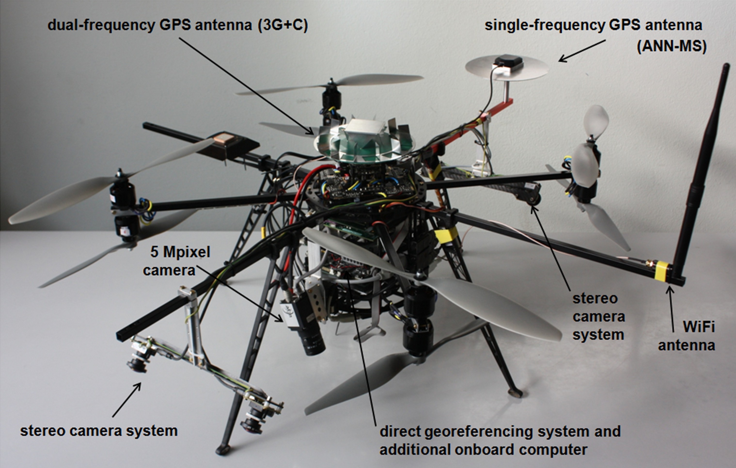
The platform: We use a quadrocopter, equipped with a GPS unit, an IMU, ultra sonic sensors, a laser scanner, a high resolution camera and four fisheye cameras (see Figure 1). One stereo camera pair points forward and one backward, each with a pitch angle of 45°. Processing power is provided by a small computer (Intel i7, 8GB RAM) which requires highly efficient algorithms for real-time applications. See Klingbeil et al. (2014) for more details on the UAV.
Official Homepage off all seven subprojects P1-7.
This website provides an overview on the research in project P4 ‘Incremental Mapping from Image Sequences’.
People: J. Schneider, T. Läbe, W. Förstner, C. Stachniss
The Bundle Adjustment BACS
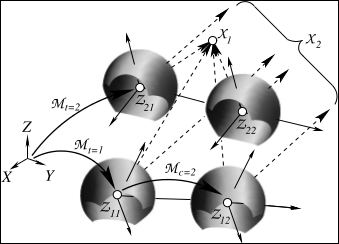
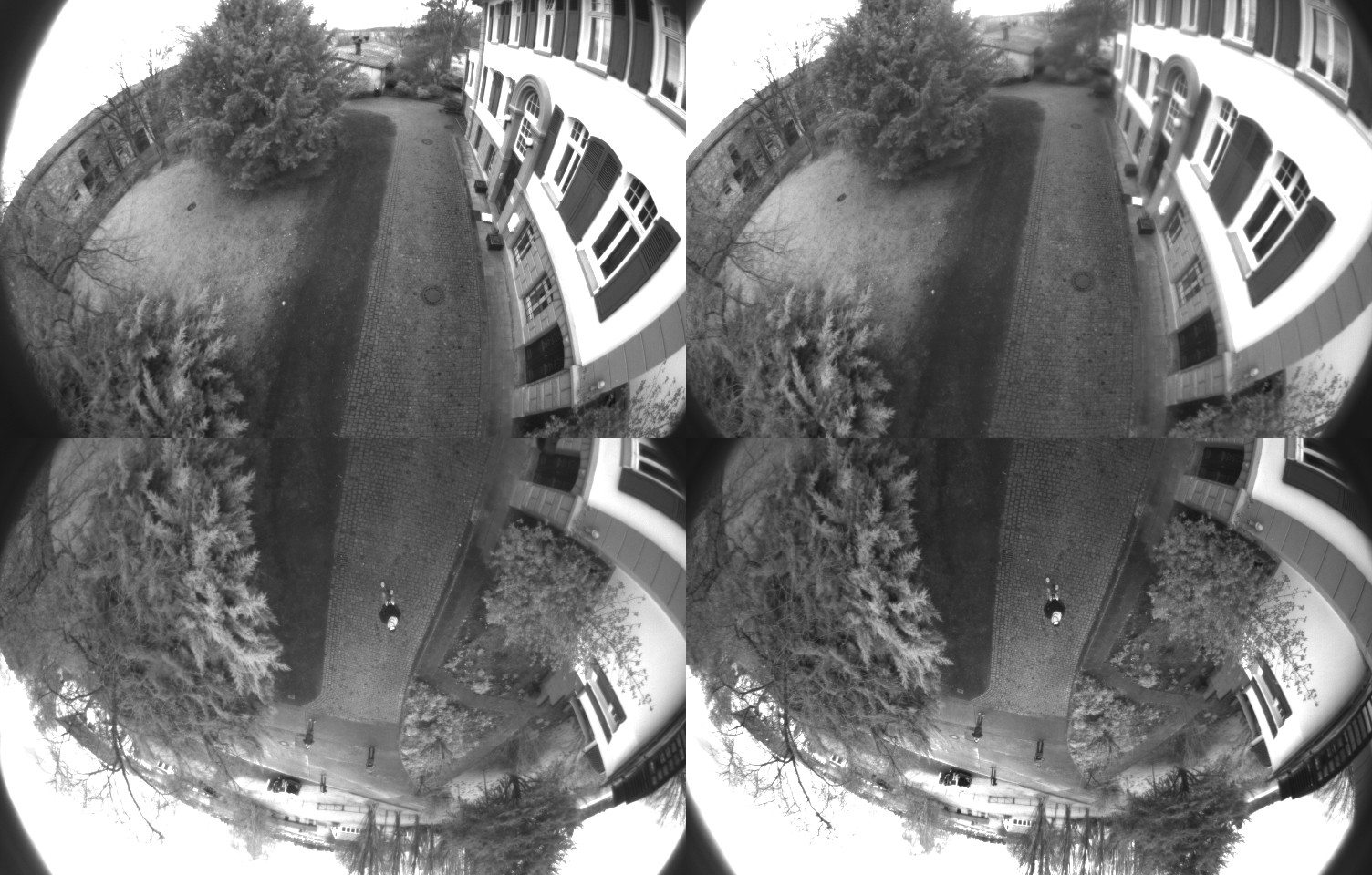
The fisheye cameras on the UAV that are mounted as two stereo pairs, one looking ahead and one looking backwards, provide a large field of view (see Figure 4). Observing bundles of rays from all directions is beneficial for the determination of the pose. We have developed the bundle adjustment BACS (‘Bundle Adjustment for Camera Systems’) which enables us to use the power of a rigorous bundle adjustment to orientate omnidirectional cameras as well as camera systems with multiple projection centers. In addition to that, BACS allows for points that are far away relative to the motion of the observing camera system. The determination of the rotational part of the motion benefits from using far points (see Figure 3). Classical bundle adjustments have numerical issues when dealing with points having small intersection angles, e.g. point X_2 in Figure 2 that lies at the horizon.
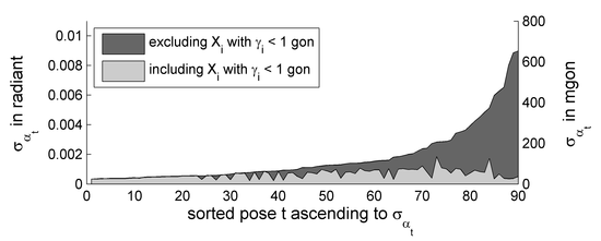
Far Points, which have a small parallactic angle and can be observed for a long time, increase the accuracy of the camera rotation significantly, see Figure 3. The integration of far points or even points at infinity as well as the use of omnidirectional multi-camera systems within a rigorous bundle adjustment is shown in Schneider et al. (2012) and the general estimation procedure in projective spaces using a minimal representation for homogeneous entities is shown in Förstner (2012).
Matlab code of software BACS: www.ipb.uni-bonn.de/bacs/
Visual Odometry with an Omnidirectional Multi-Camera System
The four cameras with Lensagon BF2M15520 fisheye lenses with a field angle up to 185° capture four image sequences triggered with a frame rate of 10Hz. The basis between the cameras amounts to 20cm providing highly overlapping views at each time of exposure, see Figure 4. The monochromatic images have a resolution of 752×480 pixels.
For a fast pose determination interest points are tracked in each image sequence using the least squares matching of the KLT tracker. The pose is determined using a fast and robust spatial resection which considers multiple projection centers and eliminates errors in the feature tracking. High frame rates can be processed as the iterative adjustment converges with the initial prediction within 2-3 fast iterations. The accuracy between two successive frames is in the order of 0.01-0.02° in the rotation and 2-3mm in the translation.
Because of the error accumulation in the feature tracking the uncertainty increases strongly, thus the map, which consists of tracked 3D points, is sequentially expanded and refined together with all poses in an incremental bundle adjustment. The bundle adjustment refers to keyframes that are selected frames initiated dependent on location and time. On each keyframe the observations from feature tracking are efficiently included into the last version of the normal equation system using the ISAM2-algorithm, see Kaess et al. (2012). The iSAM2 algorithm is very efficient as it relinearizes and solves only sub-problems that are actually influenced by the added observations. The optimization algorithm provides a globally optimal solution which in our test flights was always available within a second, see Schneider et al. (2013).
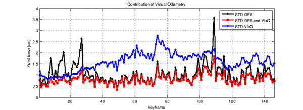
Georeferencing and long-term stability are obtained by using the poses from the fast kalman filter developed in Project P1, which processes RTK-GPS and IMU observations, as prior information for the keyframes within the bundle adjustment. Under favorable conditions we obtain a realtime accuracy of the position of about 1-2cm, see Fig. 5, and in the rotation of about 0.05-0.1°. The attainable level of accuracy is apparently independent from a possible malfunction of one sensor.
Bundle Adjustment with Map Building
A highly accurate georeferenced trajectory with a sparse reconstruction of the visible surfaces is determined by using the images of the high resolution camera (see Figure 1). The camera is triggered with 1Hz and its images are transferred via Wi-Fi to a ground station where in near real-time an incremental bundle adjustment is computed as for visual odometry on-board. Georeferencing is optionally achieved by integrating the pose from the fast Kalman filter from Project P1.
To fasten and robustify the SIFT feature matching, the search space for corresponding candidates is reduced using the poses from the fast Kalman filter or of the visual odometry. The sparse reconstruction of the environment is georeferenced as these poses are used as prior information within the incremental bundle adjustment.
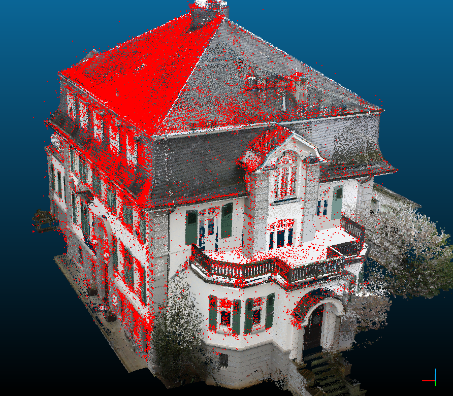
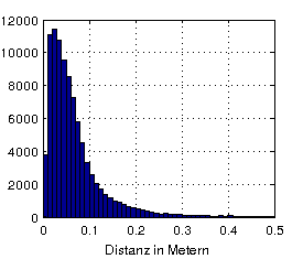
The quality of the 3D points is examined on the basis of a dense terrestrial laser scan, see Figure 6. The amount of the robust median of the differences to the nearest neighbors is smaller than 1cm in each coordinate axis, so we do not assume systematic deviations due to an incorrect calibration. The robust MAD of the distances is about 3cm and 50% of the distances are smaller than 5cm to the nearest neighbor.
Calibration
We have extended the bundle adjustment BACS to perform a system self-calibration which estimates additionally the position and orientation between the cameras in a multi-camera system in a rigorous bundle adjustment. Matches across the cameras can be determined automatically after a rotational motion of the camera system. The relative position and rotation of each camera of the kopter was determined with an accuracy of 1-3mm and below 0.01°, see Schneider and Förstner (2013).
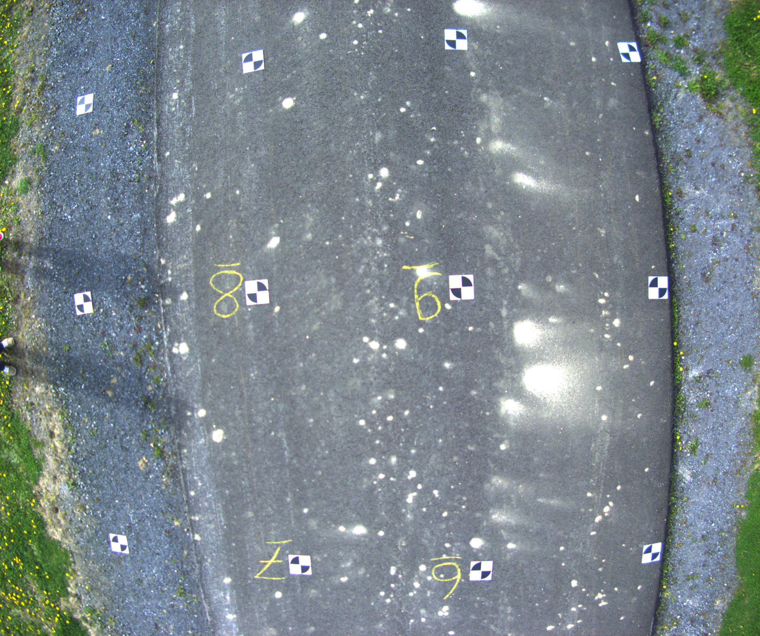
In order to integrate the poses from the fast kalman filter the offset in rotation and translation between both systems has to be determined. In a first approach we integrate GPS control points (see Figure 7) in the calibrating bundle adjustment. The offset has been determined with an accuracy of about 1cm and 0.2°.
Related Papers
- L. Klingbeil, M. Nieuwenhuisen, J. Schneider, C. Eling, D. Droeschel, D. Holz, T. Läbe, W. Förstner, S. Behnke, and H. Kuhlmann, “Towards Autonomous Navigation of an UAV-based Mobile Mapping System,” in 4th International Conf. on Machine Control & Guidance, 2014, p. 136–147.
[BibTeX] [PDF]
For situations, where mapping is neither possible from high altitudes nor from the ground, we are developing an autonomous micro aerial vehicle able to fly at low altitudes in close vicinity of obstacles. This vehicle is based on a MikroKopterTM octocopter platform (maximum total weight: 5kg), and contains a dual frequency GPS board, an IMU, a compass, two stereo camera pairs with fisheye lenses, a rotating 3D laser scanner, 8 ultrasound sensors, a real-time processing unit, and a compact PC for on-board ego-motion estimation and obstacle detection for autonomous navigation. A high-resolution camera is used for the actual mapping task, where the environment is reconstructed in three dimensions from images, using a highly accurate bundle adjustment. In this contribution, we describe the sensor system setup and present results from the evaluation of several aspects of the different subsystems as well as initial results from flight tests.
@inproceedings{klingbeil14mcg, title = {Towards Autonomous Navigation of an UAV-based Mobile Mapping System}, author = {Klingbeil, Lasse and Nieuwenhuisen, Matthias and Schneider, Johannes and Eling, Christian and Droeschel, David and Holz, Dirk and L\"abe, Thomas and F\"orstner, Wolfgang and Behnke, Sven and Kuhlmann, Heiner}, booktitle = {4th International Conf. on Machine Control \& Guidance}, year = {2014}, pages = {136--147}, abstract = {For situations, where mapping is neither possible from high altitudes nor from the ground, we are developing an autonomous micro aerial vehicle able to fly at low altitudes in close vicinity of obstacles. This vehicle is based on a MikroKopterTM octocopter platform (maximum total weight: 5kg), and contains a dual frequency GPS board, an IMU, a compass, two stereo camera pairs with fisheye lenses, a rotating 3D laser scanner, 8 ultrasound sensors, a real-time processing unit, and a compact PC for on-board ego-motion estimation and obstacle detection for autonomous navigation. A high-resolution camera is used for the actual mapping task, where the environment is reconstructed in three dimensions from images, using a highly accurate bundle adjustment. In this contribution, we describe the sensor system setup and present results from the evaluation of several aspects of the different subsystems as well as initial results from flight tests.}, url = {https://www.ipb.uni-bonn.de/pdfs/klingbeil14mcg.pdf} } - J. Schneider and W. Förstner, “Real-time Accurate Geo-localization of a MAV with Omnidirectional Visual Odometry and GPS,” in Computer Vision – ECCV 2014 Workshops, 2014, p. 271–282. doi:10.1007/978-3-319-16178-5_18
[BibTeX] [PDF]
This paper presents a system for direct geo-localization of a MAV in an unknown environment using visual odometry and precise real time kinematic (RTK) GPS information. Visual odometry is performed with a multi-camera system with four fisheye cameras that cover a wide field of view which leads to better constraints for localization due to long tracks and a better intersection geometry. Visual observations from the acquired image sequences are refined with a high accuracy on selected keyframes by an incremental bundle adjustment using the iSAM2 algorithm. The optional integration of GPS information yields long-time stability and provides a direct geo-referenced solution. Experiments show the high accuracy which is below 3 cm standard deviation in position.
@inproceedings{schneider14eccv-ws, title = {Real-time Accurate Geo-localization of a MAV with Omnidirectional Visual Odometry and GPS}, author = {J. Schneider and W. F\"orstner}, booktitle = {Computer Vision - ECCV 2014 Workshops}, year = {2014}, pages = {271--282}, abstract = {This paper presents a system for direct geo-localization of a MAV in an unknown environment using visual odometry and precise real time kinematic (RTK) GPS information. Visual odometry is performed with a multi-camera system with four fisheye cameras that cover a wide field of view which leads to better constraints for localization due to long tracks and a better intersection geometry. Visual observations from the acquired image sequences are refined with a high accuracy on selected keyframes by an incremental bundle adjustment using the iSAM2 algorithm. The optional integration of GPS information yields long-time stability and provides a direct geo-referenced solution. Experiments show the high accuracy which is below 3 cm standard deviation in position.}, doi = {10.1007/978-3-319-16178-5_18}, url = {https://www.ipb.uni-bonn.de/pdfs/schneider14eccv-ws.pdf} } - M. Nieuwenhuisen, D. Droeschel, J. Schneider, D. Holz, T. Läbe, and S. Behnke, “Multimodal Obstacle Detection and Collision Avoidance for Micro Aerial Vehicles,” in Proc. of the 6th European Conf. on Mobile Robots (ECMR), 2013. doi:10.1109/ECMR.2013.6698812
[BibTeX] [PDF]
Reliably perceiving obstacles and avoiding collisions is key for the fully autonomous application of micro aerial vehicles (MAVs). Limiting factors for increasing autonomy and complexity of MAVs (without external sensing and control) are limited onboard sensing and limited onboard processing power. In this paper, we propose a complete system with a multimodal sensor setup for omnidirectional obstacle perception. We developed a lightweight 3D laser scanner setup and visual obstacle detection using wide-angle stereo cameras. Together with our fast reactive collision avoidance approach based on local egocentric grid maps of the environment we aim at safe operation in the vicinity of structures like buildings or vegetation.
@inproceedings{nieuwenhuisen13ecmr, title = {Multimodal Obstacle Detection and Collision Avoidance for Micro Aerial Vehicles}, author = {Nieuwenhuisen, Matthias and Droeschel, David and Schneider, Johannes and Holz, Dirk and L\"abe, Thomas and Behnke, Sven}, booktitle = {Proc. of the 6th European Conf. on Mobile Robots (ECMR)}, year = {2013}, abstract = {Reliably perceiving obstacles and avoiding collisions is key for the fully autonomous application of micro aerial vehicles (MAVs). Limiting factors for increasing autonomy and complexity of MAVs (without external sensing and control) are limited onboard sensing and limited onboard processing power. In this paper, we propose a complete system with a multimodal sensor setup for omnidirectional obstacle perception. We developed a lightweight 3D laser scanner setup and visual obstacle detection using wide-angle stereo cameras. Together with our fast reactive collision avoidance approach based on local egocentric grid maps of the environment we aim at safe operation in the vicinity of structures like buildings or vegetation.}, city = {Barcelona}, doi = {10.1109/ECMR.2013.6698812}, url = {https://www.ais.uni-bonn.de/papers/ECMR_2013_Nieuwenhuisen_Multimodal_Obstacle_Avoidance.pdf} } - J. Schneider and W. Förstner, “Bundle Adjustment and System Calibration with Points at Infinity for Omnidirectional Camera Systems,” Z. f. Photogrammetrie, Fernerkundung und Geoinformation, vol. 4, p. 309–321, 2013. doi:10.1127/1432-8364/2013/0179
[BibTeX] [PDF]
We present a calibration method for multi-view cameras that provides a rigorous maximum likelihood estimation of the mutual orientation of the cameras within a rigid multi-camera system. No calibration targets are needed, just a movement of the multi-camera system taking synchronized images of a highly textured and static scene. Multi-camera systems with non-overlapping views have to be rotated within the scene so that corresponding points are visible in different cameras at different times of exposure. By using an extended version of the projective collinearity equation all estimates can be optimized in one bundle adjustment where we constrain the relative poses of the cameras to be fixed. For stabilizing camera orientations – especially rotations – one should generally use points at the horizon within the bundle adjustment, which classical bundle adjustment programs are not capable of. We use a minimal representation of homogeneous coordinates for image and scene points which allows us to use images of omnidirectional cameras with single viewpoint like fisheye cameras and scene points at a large distance from the camera or even at infinity. We show results of our calibration method on (1) the omnidirectional multi-camera system Ladybug 3 from Point Grey, (2) a camera-rig with five cameras used for the acquisition of complex 3D structures and (3) a camera-rig mounted on a UAV consisting of four fisheye cameras which provide a large field of view and which is used for visual odometry and obstacle detection in the project MoD (DFG-Project FOR 1505 “Mapping on Demand”).
@article{schneider13pfg, title = {Bundle Adjustment and System Calibration with Points at Infinity for Omnidirectional Camera Systems}, author = {J. Schneider and W. F\"orstner}, journal = {Z. f. Photogrammetrie, Fernerkundung und Geoinformation}, year = {2013}, pages = {309--321}, volume = {4}, abstract = {We present a calibration method for multi-view cameras that provides a rigorous maximum likelihood estimation of the mutual orientation of the cameras within a rigid multi-camera system. No calibration targets are needed, just a movement of the multi-camera system taking synchronized images of a highly textured and static scene. Multi-camera systems with non-overlapping views have to be rotated within the scene so that corresponding points are visible in different cameras at different times of exposure. By using an extended version of the projective collinearity equation all estimates can be optimized in one bundle adjustment where we constrain the relative poses of the cameras to be fixed. For stabilizing camera orientations - especially rotations - one should generally use points at the horizon within the bundle adjustment, which classical bundle adjustment programs are not capable of. We use a minimal representation of homogeneous coordinates for image and scene points which allows us to use images of omnidirectional cameras with single viewpoint like fisheye cameras and scene points at a large distance from the camera or even at infinity. We show results of our calibration method on (1) the omnidirectional multi-camera system Ladybug 3 from Point Grey, (2) a camera-rig with five cameras used for the acquisition of complex 3D structures and (3) a camera-rig mounted on a UAV consisting of four fisheye cameras which provide a large field of view and which is used for visual odometry and obstacle detection in the project MoD (DFG-Project FOR 1505 "Mapping on Demand").}, doi = {10.1127/1432-8364/2013/0179}, url = {https://www.dgpf.de/pfg/2013/pfg2013_4_schneider.pdf} } - J. Schneider, T. Läbe, and W. Förstner, “Incremental Real-time Bundle Adjustment for Multi-camera Systems with Points at Infinity,” in ISPRS Archives of Photogrammetry, Remote Sensing and Spatial Information Sciences, 2013, pp. 355-360. doi:10.5194/isprsarchives-XL-1-W2-355-2013
[BibTeX] [PDF]
This paper presents a concept and first experiments on a keyframe-based incremental bundle adjustment for real-time structure and motion estimation in an unknown scene. In order to avoid periodic batch steps, we use the software iSAM2 for sparse nonlinear incremental optimization, which is highly efficient through incremental variable reordering and fluid relinearization. We adapted the software to allow for (1) multi-view cameras by taking the rigid transformation between the cameras into account, (2) omni-directional cameras as it can handle arbitrary bundles of rays and (3) scene points at infinity, which improve the estimation of the camera orientation as points at the horizon can be observed over long periods of time. The real-time bundle adjustment refers to sets of keyframes, consisting of frames, one per camera, taken in a synchronized way, that are initiated if a minimal geometric distance to the last keyframe set is exceeded. It uses interest points in the keyframes as observations, which are tracked in the synchronized video streams of the individual cameras and matched across the cameras, if possible. First experiments show the potential of the incremental bundle adjustment \wrt time requirements. Our experiments are based on a multi-camera system with four fisheye cameras, which are mounted on a UAV as two stereo pairs, one looking ahead and one looking backwards, providing a large field of view.
@inproceedings{schneider13isprs, title = {Incremental Real-time Bundle Adjustment for Multi-camera Systems with Points at Infinity}, author = {J. Schneider and T. L\"abe and W. F\"orstner}, booktitle = {ISPRS Archives of Photogrammetry, Remote Sensing and Spatial Information Sciences}, year = {2013}, pages = {355-360}, volume = {XL-1/W2}, abstract = {This paper presents a concept and first experiments on a keyframe-based incremental bundle adjustment for real-time structure and motion estimation in an unknown scene. In order to avoid periodic batch steps, we use the software iSAM2 for sparse nonlinear incremental optimization, which is highly efficient through incremental variable reordering and fluid relinearization. We adapted the software to allow for (1) multi-view cameras by taking the rigid transformation between the cameras into account, (2) omni-directional cameras as it can handle arbitrary bundles of rays and (3) scene points at infinity, which improve the estimation of the camera orientation as points at the horizon can be observed over long periods of time. The real-time bundle adjustment refers to sets of keyframes, consisting of frames, one per camera, taken in a synchronized way, that are initiated if a minimal geometric distance to the last keyframe set is exceeded. It uses interest points in the keyframes as observations, which are tracked in the synchronized video streams of the individual cameras and matched across the cameras, if possible. First experiments show the potential of the incremental bundle adjustment \wrt time requirements. Our experiments are based on a multi-camera system with four fisheye cameras, which are mounted on a UAV as two stereo pairs, one looking ahead and one looking backwards, providing a large field of view.}, doi = {10.5194/isprsarchives-XL-1-W2-355-2013}, url = {https://www.int-arch-photogramm-remote-sens-spatial-inf-sci.net/XL-1-W2/355/2013/isprsarchives-XL-1-W2-355-2013.pdf} } - J. Schneider, F. Schindler, T. Läbe, and W. Förstner, “Bundle Adjustment for Multi-camera Systems with Points at Infinity,” in ISPRS Annals of Photogrammetry, Remote Sensing and Spatial Information Sciences, 2012, p. 75–80. doi:10.5194/isprsannals-I-3-75-2012
[BibTeX] [PDF]
We present a novel approach for a rigorous bundle adjustment for omnidirectional and multi-view cameras, which enables an efficient maximum-likelihood estimation with image and scene points at infinity. Multi-camera systems are used to increase the resolution, to combine cameras with different spectral sensitivities (Z/I DMC, Vexcel Ultracam) or – like omnidirectional cameras – to augment the effective aperture angle (Blom Pictometry, Rollei Panoscan Mark III). Additionally multi-camera systems gain in importance for the acquisition of complex 3D structures. For stabilizing camera orientations – especially rotations – one should generally use points at the horizon over long periods of time within the bundle adjustment that classical bundle adjustment programs are not capable of. We use a minimal representation of homogeneous coordinates for image and scene points. Instead of eliminating the scale factor of the homogeneous vectors by Euclidean normalization, we normalize the homogeneous coordinates spherically. This way we can use images of omnidirectional cameras with single-view point like fisheye cameras and scene points, which are far away or at infinity. We demonstrate the feasibility and the potential of our approach on real data taken with a single camera, the stereo camera FinePix Real 3D W3 from Fujifilm and the multi-camera system Ladybug3 from Point Grey.
@inproceedings{schneider12isprs,
title = {Bundle Adjustment for Multi-camera Systems with Points at Infinity},
author = {J. Schneider and F. Schindler and T. L\"abe and W. F\"orstner},
booktitle = {ISPRS Annals of Photogrammetry, Remote Sensing and Spatial Information Sciences},
year = {2012},
pages = {75--80},
volume = {I-3},
abstract = {We present a novel approach for a rigorous bundle adjustment for omnidirectional and multi-view cameras, which enables an efficient maximum-likelihood estimation with image and scene points at infinity. Multi-camera systems are used to increase the resolution, to combine cameras with different spectral sensitivities (Z/I DMC, Vexcel Ultracam) or - like omnidirectional cameras - to augment the effective aperture angle (Blom Pictometry, Rollei Panoscan Mark III). Additionally multi-camera systems gain in importance for the acquisition of complex 3D structures. For stabilizing camera orientations - especially rotations - one should generally use points at the horizon over long periods of time within the bundle adjustment that classical bundle adjustment programs are not capable of. We use a minimal representation of homogeneous coordinates for image and scene points. Instead of eliminating the scale factor of the homogeneous vectors by Euclidean normalization, we normalize the homogeneous coordinates spherically. This way we can use images of omnidirectional cameras with single-view point like fisheye cameras and scene points, which are far away or at infinity. We demonstrate the feasibility and the potential of our approach on real data taken with a single camera, the stereo camera FinePix Real 3D W3 from Fujifilm and the multi-camera system Ladybug3 from Point Grey.},
city = {Melbourne},
doi = {10.5194/isprsannals-I-3-75-2012},
url = {https://www.isprs-ann-photogramm-remote-sens-spatial-inf-sci.net/I-3/75/2012/isprsannals-I-3-75-2012.pdf}
}