Automatic Geometric and Semantic
Reconstruction of Buildings from Images
by Extraction of 3D-Corners and their 3D-Aggregation
Results of the 3D-Corner Reconstruction
Vertex Selection and Correspondence Analysis

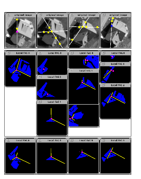
Fig 1: In the first step of the correspondence analysis the vertex in the left image was selected. It defines the epipolar lines in the remaining images on which possibly corresponding vertices have to lie. In the second step the vertex in the right image was selected as the best stereo correspondence, defining epipolar lines in the remaining images. The multi-image correspondences are give in the intersection of the epipolar lines. The bottom row shows the correspondence set which is used for deriving the 3d vertex and which forms the basis for the interpretation as a building corner.
Modelbased Feature Selection for the Parameter Estimation

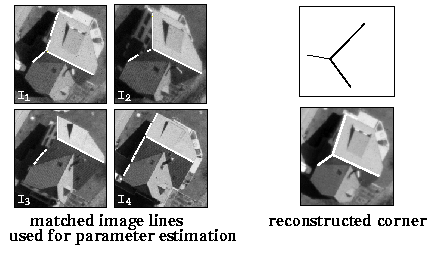
Fig 2: By backprojection of the corner hypotheses into the image and comparing it with the originally extracted image features, a model based selection of points and lines is performed. These image features are used as observation for the parameter estimation during the corner verification. The corresponding lines are shown on the left side. They compound additional lines which were not contained in the vertex correspondence set because they do not possess a neighbourhood relation to the originally selected vertex points.
Results of the 3D-Corner Aggregation

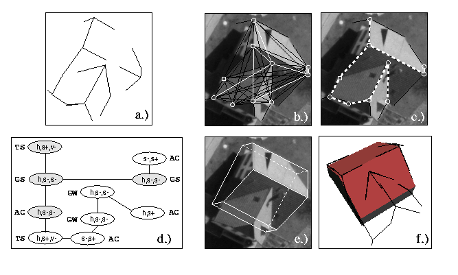
Fig 3: shows the grouping of extracted corners and their aggregation
to a parametrized saddleback roof. a.) shows the extracted corners in wire frame representation. b.) shows the derived corner connections which fulfill the class compatibility. White arcs denote non-compatible corner classes. c.) shows the
corner neighbourhood relations of corners fulfilling as well the class compatibility as the compatibility of the geometry.
The dashed arcs denote a neighbourhood relation of corners.
d.) shows the corner neighbourhood graph. The graph nodes show the unary classification of the corner lines and the corner class labels for identification. The graph arcs denote corner connenctions in the sense of a grouping of corners.
e.) wire frame representation of the aggregated saddleback roof. The graph nodes in d.) with grey background represent the subgraph which is used for indexing into the parametrized saddleback roof. The building height could not be observed and therefore has been fixed in advance. f.) Overlay of the wirefame representation of the reconstructed corners and the surface representation of the aggregated saddleback roof building.

Fig 4: a further example of reconstructed building corners and their aggregation.


